 |
| July 19, 2016 | Volume 12 Issue 27 |
Designfax weekly eMagazine

Archives
Partners
Manufacturing Center
Product Spotlight
Modern Applications News
Metalworking Ideas For
Today's Job Shops
Tooling and Production
Strategies for large
metalworking plants
Wings:
How a NASA engineer created the modern airplane wing
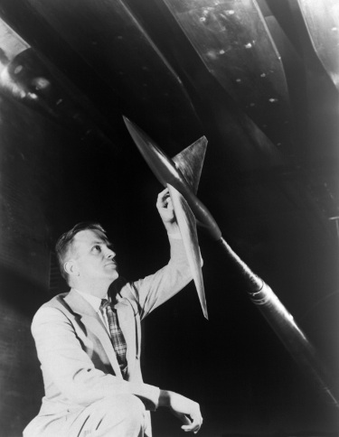
NASA engineer Richard T. Whitcomb relied on a combination of intuition and visualization more than calculations when working out new designs, and his insights revolutionized modern aeronautics. [Credits: NASA]
Once dubbed "the man who could see air," NASA engineer Richard T. Whitcomb used a combination of visualization and intuition to revolutionize modern aviation -- by turning the shape of the airplane wing on its head.
For decades, Whitcomb had been working on getting aircraft to move faster and more efficiently. By the time he was 34, he had already won the most prestigious honor in aviation, the National Aeronautic Association's 1954 Collier Trophy, for his critical work to overcome the aviation challenge of the day: the sound barrier.
Sixteen years later, he was working on improving flight efficiency at speeds just below that barrier.
"Most people have to see through testing how air moves on a model," Roy Harris, former aeronautics director at NASA's Langley Research Center, told the Washington Post in Whitcomb's 2009 obituary. "But he had this uncanny ability to accurately sense how air molecules reacted over a surface before he even built the models."
Conquering drag
The problem facing aviation engineers was that, as an airplane approached the speed of sound, the air molecules around the wings created drag, forcing the plane to work harder to maintain its speed.
"As an object moves through air, it collides with the air molecules, creating a disturbance," forming what are essentially sound waves, explains Robert Gregg, chief aerodynamicist for Boeing Commercial Airplanes. "As the object moves faster, approaching the speed of sound, these disturbances that travel at the speed of sound cannot work their way forward and instead coalesce to form a shock wave."
That was the sound barrier, which aeronautical engineers figured out how to breach in 1947. However, flying near the speed of sound -- around 660 mph at cruising altitudes, depending on air pressure and humidity -- remained highly inefficient because of the drag caused by these standing shock waves.
Whitcomb set out to conquer the drag. And his bosses at NASA were eager to help him lend his particular brand of genius to the problem. "Though he had a conservative, shy personality, he was a radical in the laboratory," NASA historian James Hansen wrote of Whitcomb in his history of Langley. "In some respects, management did not know exactly how to deal with him. The best idea any of his supervisors came up with was to leave him alone." Any administrative details slowing him down could be taken care of later.
Today, nearly every commercial airplane bears the marks of Whitcomb's several innovations. Over the decades, the increases in efficiency have saved the airline industry billions of dollars in fuel every year, which also means significant reductions in greenhouse gas emissions. [Credits: iStock/Justin Sullivan]
Overall, Whitcomb came up with three important aeronautical innovations while working at NASA Langley, one in each decade of his career.
In the 1950s, Whitcomb created the area rule (wasp waist) design that gave supersonic aircraft the pinched "coke bottle" look to reduce aerodynamic drag and increase transonic speed without added power. If the area rule was Whitcomb's major accomplishment of the 1950s, his supercritical wing revolutionized the design of jet liners after the 1960s. In this case, the key was the development of an airfoil that was flatter on the top and rounder on the bottom with a downward curve on the trailing edge. That shape delayed the onset of drag, increasing the fuel efficiency of aircraft flying close to the speed of sound. In the 1970s, it was an article on soaring birds that led Whitcomb to develop his third significant innovation -- winglets -- refining an idea that had been around for decades.
Winging it
Obsessed with the aerodynamics of flight since his childhood, Whitcomb was famous for his single-track focus. He never married, and he often worked two shifts per day, sleeping on a cot at the high-speed wind tunnel facility. His nephew, David Whitcomb, told the New York Times that NASA accountants scolded his uncle more than once for letting his paychecks expire while he used them as bookmarks.
Unlike many engineers, Whitcomb skipped the calculations and went straight to a physical model.
For the supercritical wing, he started with a conventional wing design and, relying on intuition, used auto body putty to add bulk to some areas while filing away others, testing and retesting his models in Langley's high-speed wind tunnel. He came up with something he called the "supercritical" airfoil. The end result almost looked upside-down compared with standard wings of the day, because it was nearly flat on top and rounded on the bottom. It was also thicker than the norm, especially on its blunt leading edge.
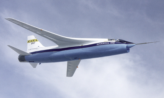
NASA TF-8A supercritical wing testbed in 1973.
Around the speed of sound, the flatter top minimized the effect of the standing shock wave that formed on the wing, while a downward-curving underside compensated with additional lift. The added thickness also provided a sturdier attachment to the fuselage, allowing for less reinforcing structure and, hence, a lighter wing.
Early testing showed the supercritical wing increased a plane's efficiency by as much as 15 percent. And it turned out that the wings were more efficient at subsonic speeds as well.
In the case of the winglets, other engineers had suspected that end plates added to the wing tips could reduce drag. The concept of winglets originated with a British aerodynamicist in the late 1800s, but the idea remained on the drawing board until it was rekindled in the early 1970s by Whitcomb -- a time when the price of aviation fuel started spiraling upward.
But the Langley engineer proved a simple vertical plate wasn't enough. "It is a little wing. That's why I called them winglets," said Whitcomb. "It's designed with all the care that a wing was designed." Winglets reduce yet another type of drag and further improve aerodynamic efficiency. Many airliners and private jets sport wingtips that are angled up for better fuel performance.
Video: Interview with Richard "Dick" Whitcomb.
Winglets increase an aircraft's operating efficiency by reducing what is called induced drag at the tips of the wings. An aircraft's wing is shaped to generate negative pressure on the upper surface and positive pressure on the lower surface as the aircraft moves forward. This unequal pressure creates lift across the upper surface and the aircraft is able to leave the ground and fly.
Unequal pressure, however, also causes air at each wingtip to flow outward along the lower surface, around the tip, and inboard along the upper surface producing a whirlwind of air called a wingtip vortex. The effect of these vortices is increased drag and reduced lift that results in less flight efficiency and higher fuel costs.
Winglets, which are airfoils operating just like a sailboat tacking upwind, produce a forward thrust inside the circulation field of the vortices and reduce their strength. Weaker vortices mean less drag at the wingtips, and lift is restored. Improved wing efficiency translates to more payload, reduced fuel consumption, and a longer cruising range that can allow an air carrier to expand routes and destinations.
To produce as much forward thrust as possible, the winglet's airfoil is designed with the same attention as the airfoil of the wings themselves. Performance improvements generated by winglets, however, depend on factors such as the basic design of the aircraft, engine efficiency, and even the weather in which an aircraft is operating.
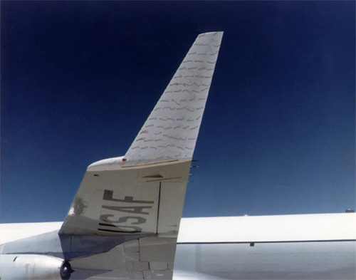
Close-up of winglet on KC-135 test aircraft, with attached tufts displaying flow of air over winglet surface. [NASA Photo EC79-11481]
The shapes and sizes of winglets, and the angles at which they are mounted with respect to the main wings, differ between the many types and sizes of aircraft produced, but they all represent improved efficiency. Throughout the aviation industry, winglets are responsible for increased mileage rates of as much as 7 percent.
Aircraft manufacturers and makers of add-on winglets have also reported improved cruising speeds, time-to-climb rates, and higher operating altitudes.
Studies at Langley also included tests of a DC-10 model in a wind tunnel that showed that the winglets on the model reduced overall drag by 5 percent compared to the model without the devices. These tests were followed by a Boeing engineering study of a 747 with winglets, and a prediction that a 4 percent drag reduction would result. These positive conclusions, coupled with Whitcomb's work, prompted the U.S. Air Force to consider the possible installation of winglets on KC-135 and C-141 transport aircraft.
The winglet flight test program brought together NASA, the U.S. Air Force, and Boeing, which began the effort with configuration studies and contractual work to design and manufacture the test articles which measured 9 ft high and 6 ft across at the base. Wind tunnel studies were carried out at Langley where researchers tested the winglet models at various air speeds and also in a variety of flap and aileron configurations to validate the design work. Wind tunnel results predicted a 6 percent drag reduction on the winglet-equipped test aircraft.
The U.S. Air Force furnished the KC-135 test aircraft. It was delivered to Dryden in late 1977 for the installation of sensors and recorders that would obtain in-flight performance data. The winglets and the test aircraft's modified outer wing panels arrived at Dryden from Boeing in May 1979, setting up an installation and checkout period that climaxed with the program's first test flight on July 24, 1979.
During the 48-flight test program, the winglets -- designed with a general-purpose airfoil that remained the same from root to tip -- could be adjusted to seven different cant and incidence angles to give researchers a broad picture of their performance in a variety of flight conditions.
The major areas of study during the program were aerodynamic loads on the winglets; distribution of air pressure over their surfaces; how they affected the test aircraft's stability and control; susceptibility to buffeting and flutter; and drag reduction.
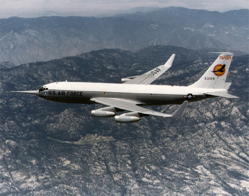
Air Force KC-135 test aircraft in flight during NASA winglets study. [NASA Photo EC79-11484]
Flight conditions in which test data was obtained included a cruise speed of about 500 mph at altitudes of 30,000 to 35,000 ft; push-over and pull-up maneuvers; steady-state sideslips with the nose both left and right; accelerated turns and banks; and elevator, rudder, and aileron raps to set up flutter and buffeting conditions. During these test conditions, the aircraft handled and behaved as predicted and expected.
Among the seven cant and incidence angles tested, the combination that produced the best results was a 15-degree cant angle and an incidence angle of -4 degrees.
Test results closely matched the original predictions of Whitcomb and data produced in the pre-flight wind tunnel studies: Winglets on the KC-135 test aircraft increased its fuel mileage rate by 6.5 percent -- better than the 6 percent projected by the wind tunnel studies.
Source: Compiled from NASA reports
Published July 2016
Rate this article
View our terms of use and privacy policy